Saturday, June 30, 2012

---( ) Output Coil


---(   )  Output Coil
Symbol 
<address>
---(    )

Parameter       Data Type      Memory Area        Description
<address>          BOOL       I, Q, M, L, D         Assigned bit

Description 
---(   ) (Output Coil) works like a coil in a relay logic diagram. If there is power flow to the coil
(RLO = 1), the bit at location <address> is set to "1". If there is no power flow to the coil (RLO = 0),
the bit at location <address> is set to "0". An output coil can only be placed at the right end of a ladder
rung. Multiple output elements (max. 16) are possible (see example). A negated output can be created
by using the ---|NOT|--- (invert power flow) element.
MCR (Master Control Relay) dependency
MCR dependency is activated only if an output coil is placed inside an active MCR zone. Within an
activated MCR zone, if the MCR is on and there is power flow to an output coil; the addressed bit is
set to the current status of power flow. If the MCR is off, a logic "0" is written to the specified address
regardless of power flow status.
Status word
           BR  CC 1  CC 0  OV  OS  OR  STA  RLO  /FC
writes:   -       -        -       -     -     0     X     -       0


The signal state of output Q4.0 is "1" if one of the following conditions exists:
The signal state is "1" at inputs I0.0 and I0.1
Or the signal state is "0" at input I0.2.
The signal state of output Q4.1 is "1" if one of the following conditions exists:
The signal state is "1" at inputs I0.0 and I0.1
Or the signal state is "0" at input I0.2 and "1" at input I0.3

If the example rungs are within an activated MCR zone:
When MCR is on, Q4.0 and Q4.1 are set according to power flow status as described above.
When MCR is off (=0), Q4.0 and Q4.1 are reset to 0 regardless of power flow. !--RELATED-POSTS-STARTS-->

--|NOT|-- Invert Power Flow


--|NOT|-- Invert Power Flow 
Symbol 
 ---|NOT|---
Description
---|NOT|--- (Invert Power Flow) negates the RLO bit.
Status word 


                 BR   CC 1   CC 0   OV   OS   OR   STA   RLO   /FC

writes:   -        -          -        -      -      -       1       X         -


The signal state of output Q4.0 is "0" if one of the following conditions exists:
The signal state is "1" at input I0.0
Or the signal state is "1" at inputs I0.1 and I0.2. !--RELATED-POSTS-STARTS-->

Friday, June 29, 2012

XOR Bit Exclusive OR


XOR  Bit Exclusive OR
For the XOR function, a network of normally open and normally closed contacts must be created as
shown below.
Symbols
<address1> <address2>


Parameter Data Type  Memory Area Description
<address1>  BOOL  I, Q, M, L, D, T, C  Scanned bit
<address2  BOOL  I, Q, M, L, D, T, C  Scanned bit

Description
XOR (Bit Exclusive OR) creates an RLO of "1" if the signal state of the two specified bits is different.


The output Q4.0 is "1" if (I0.0 = "0" AND I0.1 = "1") OR (I0.0 = "1" AND I0.1 = "0"). !--RELATED-POSTS-STARTS-->

---| / |--- Normally Closed Contact (Address)


---| / |---    Normally Closed Contact (Address) 
Symbol 
<address>
  ---| / |---

Parameter Data Type  Memory Area Description
<address>  BOOL  I, Q, M, L, D, T, C  Checked bit
Description
---| / |--- (Normally Closed Contact) is closed when the bit value stored at the specified <address> is
equal to "0". When the contact is closed, ladder rail power flows across the contact and the result of
logic operation (RLO) = "1".
Otherwise, if the signal state at the specified <address> is "1", the contact is opened. When the
contact is opened, power does not flow across the contact and the result of logic operation
(RLO) = "0".
When used in series, ---| / |--- is linked to the RLO bit by AND logic. When used in parallel, it is linked
to the RLO by OR logic.
Status word

                      BR  CC 1  CC 0  OV  OS  OR  STA  RLO  /FC
writes:              -      -        -       -     -      X     X     X      1


Power flows if one of the following conditions exists:
The signal state is "1" at inputs I0.0 and I0.1
Or the signal state is "1" at input I0.2
!--RELATED-POSTS-STARTS-->

Thursday, June 28, 2012

Memory area/Data area


I,Q Memory area
Input output bit ,I is use as switch and Q is use as relay and external output is possible When cpu power is On or RUN.


M (Memory bit):Auxiliary relay 
As an internal relay inside PLC, direct external output is impossible, but if connected with I/O , it will be
then possible. When power is On or RUN, other areas than specified as latch area by parameter setting
will be all eliminated to 0.


C: counter memory

A counter is a function element of the STEP 7 programming language that acounts. Counters have an area reserved for them in the memory of your CPU. This memory area reserves one 16-bit word for each counter. The statement list instruction/LAD set supports 256 counters. To find out how many counters are available in your CPU, please refer to the CPU technical data.

Counter instructions are the only functions with access to the memory area.


T(Timer) Area in Memory

Timers have an area reserved for them in the memory of your CPU. This memory area reserves one 16-bit word for each timer address. The ladderlogic instruction set supports 256 timers. Please refer to your CPU’s technical information to establish the number of timer words available.

The following functions have access to the timer memory area:

· Timer instructions

· Updating of timer words by means of clock timing. This function of your CPU in the RUN mode decrements a given time value by one unit at the interval designated by the time base until the time value is equal to zero.

Time Value

Bits 0 through 9 of the timer word contain the time value in binary code. The time value specifies a number of units. Time updating decrements the time value by one unit at an interval designated by the time base. Decrementing continues until the time value is equal to zero. You can load a time value into the low word of accumulator 1 in binary, hexadecimal, or binary coded decimal (BCD) format.

You can pre-load a time value using either of the following formats:

· W#16#wxyz

· Where w = the time base (that is, the time interval or resolution)

· Where xyz = the time value in binary coded decimal format

· S5T#aH_bM_cS_dMS

· Where H = hours, M = minutes, S = seconds, and MS = milliseconds;
a, b, c, d are defined by the user.

· The time base is selected automatically, and the value is rounded to the next lower number with that time base.

The maximum time value that you can enter is 9,990 seconds, or 2H_46M_30S.

S5TIME#4S = 4 seconds
s5t#2h_15m = 2 hours and 15 minutes
S5T#1H_12M_18S = 1 hour, 12 minutes, and 18 seconds

Time Base

Bits 12 and 13 of the timer word contain the time base in binary code. The time base defines the interval at which the time value is decremented by one unit. The smallest time base is 10 ms; the largest is 10 s.

Time Base Binary Code for the Time Base
10 ms 00
100 ms 01
1 s 10
10 s 11
Values that exceed 2h46m30s are not accepted. A value whose resolution is too high for the range limits (for example, 2h10ms) is truncated down to a valid resolution. The general format for S5TIME has limits to range and resolution as shown below:

Resolution Range
0.01 second 10MS to 9S_990MS
0.1 second 100MS to 1M_39S_900MS
1 second 1S to 16M_39S
10 seconds 10S to 2H_46M_30S
Bit Configuration in the Time Cell

When a timer is started, the contents of the timer cell are used as the time value. Bits 0 through 11 of the timer cell hold the time value in binary coded decimal format (BCD format: each set of four bits contains the binary code for one decimal value). Bits 12 and 13 hold the time base in binary code.

The following figure shows the contents of the timer cell loaded with timer value 127 and a time base of 1 second


Different typesTimer
S_PULSE:Pulse timer The maximum time that the output signal remains at 1 is the same as the programmed time value t. The output signal stays at 1 for a shorter period if the input signal changes to 0.
S_PEXT:Extended pulse timer The output signal remains at 1 for the programmed length of time, regardless of how long the input signal stays at 1.
S_ODT:On-delay timer The output signal changes to 1 only when the programmed time has elapsed and the input signal is still 1.
S_ODTS:Retentive on-delay timer The output signal changes from 0 to 1 only when the programmed time has elapsed, regardless of how long the input signal stays at 1.
S_OFFDT:
Off-delay timer The output signal changes to 1 when the input signal changes to 1 or while the timer is running. The time is started when the input signal changes from 1 to 0.


!--RELATED-POSTS-STARTS-->

---| |--- Normally Open Contact (Address)


---|   |---  Normally Open Contact (Address) 
Symbol 
      <address>
       ---|   |---

Parameter     Data Type        Memory Area             Description
<address>     BOOL          I, Q, M, L, D, T, C        Checked bit

Description
---|  |--- (Normally Open Contact) is closed when the bit value stored at the specified <address> is
equal to "1". When the contact is closed, ladder rail power flows across the contact and the result of
logic operation (RLO) = "1".
Otherwise, if the signal state at the specified <address> is "0", the contact is open. When the contact
is open, power does not flow across the contact and the result of logic operation (RLO) = "0".
When used in series, ---|  |---    is linked to the RLO bit by AND logic. When used in parallel, it is
linked to the RLO by OR logic.
Status word

            BR  CC 1  CC 0  OV  OS  OR  STA  RLO  /FC
writes:    -     -        -        -     -      X     X       X     1


Power flows if one of the following conditions exists:
The signal state is "1" at inputs I0.0 and I0.1
Or the signal state is "1" at input I0.2 !--RELATED-POSTS-STARTS-->

Status word description

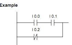
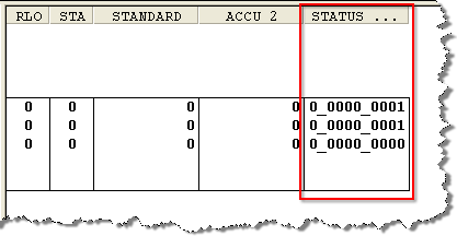
The status word can be seen by displaying the STATUS column while monitoring in STL view.  The RLO (bit 1) and the STA (bit 2) are also displayed in the RLO and STA column.


BR        Binary Result Bit (Status Word, Bit 8)

The BR bit is bit 8 of the status word.
The BR bit transfers the results obtained from processing Statement List (STL) instructions on to the next instructions to be processed.

The Binary Result transfers the result of the operations
onto the next instruction for reference.  When the BR bit is 1 it enables the output
of the block (ENO) to be TRUE and thus allow other blocks after it to be
processed.  The SAVE, JCB and JNB instructions set the BR bit.

· If an error occurred during execution, the BR bit is ‘’0”.

· If the function was executed with no error, the BR bit is ‘’1”.


CC 1, CC 0        Condition Codes (Status Word, Bits 6 and 7)

The Condition Code bits provide results for comparison and math instructions.
Comparison Instructions
CC 1
CC 0
Meaning
0
0
ACCU 2 = ACCU 1
0
1
ACCU 2 < ACCU 1
1
0
ACCU 2 > ACCU 1
1
1
Unordered (floating point comparison only)
Math Instructions, without Overflow
CC 1
CC 0
Meaning
0
0
Result = 0
0
1
Result < 0
1
0
Result > 0
Integer Math Instructions, with Overflow
CC 1
CC 0
Meaning
0
0
Negative range overflow in ADD_I and ADD_DI
0
1
Negative range overflow in MUL_I and MUL_DI
1
0
Negative range overflow in ADD_I, ADD_DI, SUB_I, and SUB_DI
1
1
Division by 0 in DIV_I, DIV_DI, and MOD_DI
Floating Point Math Instructions, with Overflow
CC 1
CC 0
Meaning
0
0
Gradual underflow
0
1
Negative range overflow
1
0
Positive range overflow
1
1
Not a valid floating-point number
Shift and Rotate Instructions
CC 1
CC 0
Meaning
0
0
Bit shifted out = 0
1
0
Bit shifted out = 1
Word Logic Instructions
CC 1
CC 0
Meaning
0
0
Result = 0
1
0
Result <> 0


OV        Overflow (Status Word, Bit 5)

The OV bit displays errors for math instructions or comparison instructions with floating point numbers.

The OV bit is bit 5 of the status word.

It is set by a math instruction with floating point numbers after a fault has occurred (overflow, illegal operation, comparison unordered). The OV bit is reset when the fault is eliminated.


OS        Overflow Stored (Status Word, Bit 4)

The OS bit stores the OV bit if an error occurs during math instructions or comparison instructions with floating point numbers.

The OS bit is bit 4 of the status word.

The OS bit is set, together with the OV (Overflow) bit, in the event of a fault. It remains set after the fault has been eliminated. It thus stores the OV bit status and indicates whether or not a fault has occurred in one of the previously executed instructions.

The following commands reset the OS bit:

· JOS (Jump if OS=1)

· Block call instructions

· Block end instructions


OR        (Status Word, Bit 3)

The OR bit is used for combining AND functions before OR functions.

The OR bit is status word bit 3.

The OR bit is set if the RLO of the AND logic operation is 1. This anticipates the result of the OR logic operation. Every other bit-processing instruction resets the OR bit.


STA        Status Bit (Status Word, Bit 2)

The STA bit stores the value of an addressed bit.

The STA bit is bit 2 of the status word.

The status of a bit logic instruction that performs a read access to memory (A, AN, O, ON, X, or XN) is always the same as the value of the addressed bit. The status of a logic instruction that may perform a write access to the memory (R, S, or =) is the same as the value of the written bit or, if writing is not performed, the same as the value of the addressed bit. The status bit has no significance for bit instructions that do not access the memory. These instructions set STA to 1. The status bit is not read by instructions, it is interpreted for you when viewing the online status of program variables.


RLO        Result of Logic Operation (Status Word, Bit 1)

The RLO bit stores the result of a logic operation string or comparison instruction.

The RLO bit is status word bit 1.

The first instruction in a segment checks the contact signal state. The RLO is set to ‘’1’’ if the check is executed. The second instruction also checks the contact signal state. This check result is now combined with the value stored in the RLO bit according to the Boolean algebra rules and stored in the RLO bit. This logic string ends after an assignment or a conditional jump. Depending on the RLO bit value, an assignment or a conditional jump is executed.


/FC        First Check Bit (Status Word, Bit 0)

The /FC bit signal state controls a logic operation string.

The /FC bit is status word bit 0.

Each logic operation queries the /FC bit signal state and the addressed contact.

· If the /FC bit signal state equals ‘’1,’’ an instruction logically combines the result of its signal state check on its addressed contact with the RLO generated since the first check and stores the result in the RLO bit.

· If the /FC bit signal state equals ‘’0,’’ the logic string begins with a first check.

The logic string ends and the /FC bit is set to ‘’0’’ with the assignment of a value (S,R,=) or with a RLO-dependent jump instruction.


!--RELATED-POSTS-STARTS-->

Statu Word


Status word bits are read and written by the CPU and directly by your program statements.

As each of your instructions is processed, CPU status word bits are used according to the function of each instruction. Status word bits are used to link your instructions together and to provide immediate results and error information. Your program statements can then read status word bits and take action, if necessary.

Status Word

BR CC 1 CC 0 OV OS OR STA RLO   /FC

Notation for an instruction’s effect upon the status word:
- No read or write
* Read
x May write "1" or "0"
0 Reset to "0"
1 Set to "1"

Status Word in STL Monitor
See also:
CPU Resister !--RELATED-POSTS-STARTS-->

Bit Logic Instructions


Overview of Bit Logic Instructions 
Description : 
Bit logic instructions work with two digits, 1 and 0. These two digits form the base of a number system
called the binary system. The two digits 1 and 0 are called binary digits or bits. In the world of contacts
and coils, a 1 indicates activated or energized, and a 0 indicates not activated or not energized.
The bit logic instructions interpret signal states of 1 and 0 and combine them according to Boolean
logic. These combinations produce a result of 1 or 0 that is called the ”result of logic operation” (RLO).
The logic operations that are triggered by the bit logic instructions perform a variety of functions.
There are bit logic instructions to perform the following functions:
•  ---|   |---  Normally Open Contact (Address)
 ---| / |---  Normally Closed Contact (Address)
 ---(SAVE)  Save RLO into BR Memory
 XOR  Bit Exclusive OR
•  ---(  )  Output Coil
•  ---( # )---  Midline Output
•  ---|NOT|---  Invert Power Flow
The following instructions react to an RLO of 1:
•  ---( S )  Set Coil
 ---( R )  Reset Coil
•  SR  Set-Reset Flip Flop
 RS  Reset-Set Flip Flop
Other instructions react to a positive or negative edge transition to perform the following functions:
 ---(N)---  Negative RLO Edge Detection
•  ---(P)---  Positive RLO Edge Detection
•  NEG  Address Negative Edge Detection
•  POS  Address Positive Edge Detection
• Immediate  Read
• Immediate  Write !--RELATED-POSTS-STARTS-->

What is an HMI?

What is an HMI? HMI stands for Human Machine Interface. This is the interface between the operator and the controller. The HMI is the controller operating panel. The panel comprises a numeric keypad and a LCD screen that displays text. The keypad is used to input data into the application, such as Timer values. The PLC's Display screen can show operator messages, variable information from the program and system information. HMI messages are created in the Display Editor. Variable information fields are created in the Variable Editor. Today most of the HMI are Touch screen but Normal computer can used which need some more arrangement.
!--RELATED-POSTS-STARTS-->

Types of PLC Programing Language

PLC user program is under the control system designer process control requirements, through the establishment of PLC programming language design. Developed by the International Electrotechnical Commission standard industrial control programming language (IE PLC user program is under the control system designer process control requirements, through the establishment of PLC programming language design.
The five languages in the IEC Standard 61131-3 are:

Instruction List (IL): A low-level language very similar to assembly language. The code is compact and suitable for small projects. It not very powerful. The other languages are easier to use and document. It has been years since I have used it and do not miss it.
Structured Text (ST): A high level language structured like Pascal. Users trained in high level text languages would be comfortable with ST.
Ladder Diagrams (LD): Also commonly known as Ladder Logic. Modeled after the electrical wiring of contacts and relays used to create logic. It made the transition from Relay logic (using actually electrical relays) to the PLC easier. It falls short when tasks become complex. Not the best for modular PLC programming. This language will look very familiar to Electricians.
Function Block Diagram (FBD): The blocks contain procedures or functions to act on the input "wires" and output the result. It lends itself readily to standardizing, modulating, and maintaining programs. I prefer this over LD, and many are coming to realize its advantages. Ladder Diagrams will die a slow death.
Sequential Function Chart (SFC): This graphic language is great for concurrent parallel sequential operations. It is self documenting. It very useful pulling together in a flow chart form the other PLC programming elements such as function blocks (FB) or structured text (ST). Its format shows overall program flow very well making it faster and easier to understand what the program is doing. Easy to identify the section of interest for troubleshooting and program improvement.
By the way...a common belief is that you would be able to quickly convert between the above languages. This is false. Although they have common elements they also have differences that preclude the possibility.


Ref:http://www.plcedge.com !--RELATED-POSTS-STARTS-->

Monday, June 25, 2012

What is PLC & how it work


PLCs are often defined as miniature industrial computers that contain hardware and software that is used to perform control functions. A PLC consists of two basic sections: the central processing unit (CPU) and the input/output interface system. The CPU, which controls all PLC activity, can further be broken down into the processor and memory system. The input/output system is physically connected to field devices (e.g., switches, sensors, etc.) and provides the interface between the CPU and the information providers (inputs) and controllable devices (outputs).
To operate, the CPU "reads" input data from connected field devices through the use of its input interfaces, and then "executes", or performs the control program that has been stored in its memory system. Programs are typically created in ladder logic, a language that closely resembles a relay-based wiring schematic, and are entered into the CPU's memory prior to operation. Finally, based on the program, the PLC "writes", or updates output devices via the output interfaces. This process, also known as scanning, continues in the same sequence without interruption, and changes only when a change is made to the control program.

A brief history
The first PLC can be traced back to 1968 when Bedford Associates, a company in Bedford, MA, developed a device called a Modular Digital Controller for General Motors (GM). The MODICON, as it was known, was developed to help GM eliminate traditional relay-based machine control systems. Because relays are mechanical devices, they have limited lifetimes. They are also cumbersome, especially in large applications where thousands of them may exist. With so many relays to work with, wiring and troubleshooting could be quite complicated.
Since the MODICON was an electronic device, not a mechanical one, it was perfect for GM's requirements, as well as for many other manufacturers and users of control equipment. With less wiring, simpler troubleshooting, and easy programming, PLC technology caught on quickly.

Today's PLC
As PLC technology has advanced, so have programming languages and communications capabilities, along with many other important features. Today's PLCs offer faster scan times, space efficient high-density input/output systems, and special interfaces to allow non-traditional devices to be attached directly to the PLC. Not only can they communicate with other control systems, they can also perform reporting functions and diagnose their own failures, as well as the failure of a machine or process.
Size is typically used to categorize today's PLC, and is often an indication of the features and types of applications it will accommodate. Small, non-modular PLCs (also known as fixed I/O PLCs) generally have less memory and accommodate a small number of inputs and outputs in fixed configurations. Modular PLCs have bases or racks that allow installation of multiple I/O modules, and will accommodate more complex applications.
When you consider all of the advances PLCs have made and all the benefits they offer, it's easy to see how they've become a standard in the industry, and why they will most likely continue their success in the future.

Which one is right for you?
So you've learned a little bit about PLCs and have decided that a PLC-based control system is the right choice for you. Now what?

The next step is to select the right system. But how do you do that? Where do you begin when there are so many manufacturers and so many different PLC models?
A drawing of the machine or process is a good start. This can help identify field devices and physical requirements for hardware locations. From the drawing, you can determine how many analog and/or discrete devices you will have. Discrete devices are those that operate in only two states: on and off. Examples of discrete devices include pushbuttons and switches. Analog devices, such as thermocouples, process transducers, and display meters, will supply or accept signals within a specified range, typically 0-10 volts or 4-20 mA.
Once the field device requirements and hardware locations are defined, you can begin the process of choosing a PLC that will meet your requirements. The worksheet on the following page is a basic summary of considerations for determining the type of PLC you will need, regardless of which manufacturers you are evaluating. Armed with this information, the next steps will be selecting, designing, programming, and installing your system.
When choosing a PLC, there are many factors to consider that, if not properly planned for, may affect your system's performance after installation. With proper planning, the selection of a PLC system can be done with relative ease.

!--RELATED-POSTS-STARTS-->